Add COM Port Device Ethernet Remote I/O Module M140T

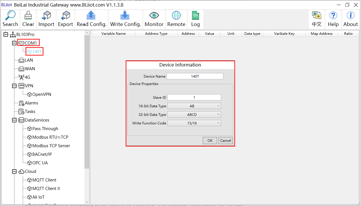
1.Click COM2, right click the mouse and click Add to enter configuration box.
2.Set device name, for example, set M140T as device name.
3.Input device modbus adress, for example, if M140T Modbus ID is 1, put 1.
4.Select Type of data to be collected. The example is to collect the DI and DO of the M140T, both of which are Boolean type, not numeric type register, select as default.
5.Write function code: As default, M140T supports writing multiple registers.
6.Click OK to confirm adding M140T.
7.Click COM1 to view the added device M140T. If more devices to be added, perform the same procedures as above Step 1-6.
Note: Click Write Configuration. Gateway BL110 will restart automatically. After restarting, M140T is added successfully.
Add COM Port Device M140T Datapoint

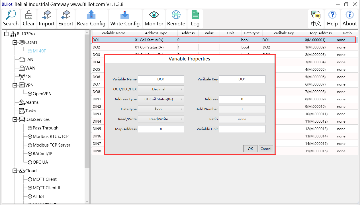
1.Click M140T, move mouse cursor to the right box, right click mouse to enter datapoint configuration window.
2.Variable name: Set datapoint name, for example, DO1.
3.Variable key, which can be filled in arbitrarily. The identifier cannot be repeated, for example, the MQTT identifier of the DO1 data point is filled in as DO1.
4.Select the acquisition address and choose data format according to the requirements, OCT/DEC/HEX are octal/decimal/hexadecimal respectively. The collected Modbus protocol address is input in decimal, so the example selects decimal.
5.Address type: Select according to the function codes supported by the collected data points. For example, the DO of the collected M140T supports the "01" function code, so select "01 Coil Status", and DI supports the "02" function code, so select "02 Input Status”.
6.Address: the register address of the data point, such as: data point DO1 is "0" register address in the M140T, so fill in "0".
7.Data type: Select according to the data point, such as: DI and DO of M140T are both coil types, so select "bool".
8.Add Number: If it is collecting continuous addresses, the same function code can be collected multiple times.
9.Read/Write:Automatic identifying read-write type according to Address Type.
10.Map address: fill in the address where the collected data points are stored to the BL110 gateway device, which can be filled in at will. Mapped addresses cannot be duplicated. Range: 0-2000. For example, the data collected from DO1 is stored in the “0” register address of the BL110 gateway. The outside of the mapping address on the configuration software represents the Modbus address, and M.XXX represents the PLC Modbus address.
11.Variable Unit: Input any required unit.
12.Click OK to confirm.
Note: After clicking OK to confirm the configuration, datapoints will appear in the box lik above picture. If more datapoints to be added, right click the box and click Add to enter datapoint configuration box, repeat Step 2-12.
Note: Click Write Configuration. Gateway will restart automatically. After restarting, M140T datapoints are added successfully.

